Showing posts with label mixer schematic. Show all posts

Simple mixer circuit – Common base

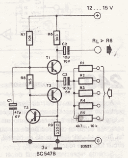
The simple mixer schematic is built on common base principle, where input voltages are transformed in alternative currents wich are summed to form the alternative current component for the collector. The total amplification is R6 - Ri, where Ri is one of the input resistors. I’ve build this mixer for a little transmitter and works great.

Simple mixer circuit – Common base


Simple mixer circuit – Common base
source :http://electroschematics.com READ MORE...

Simple mixer circuit – Common base

The simple mixer schematic is built on common base principle, where input voltages are transformed in alternative currents wich are summed to form the alternative current component for the collector. The total amplification is R6 - Ri, where Ri is one of the input resistors. I’ve build this mixer for a little transmitter and works great.

Simple mixer circuit – Common base


Simple mixer circuit – Common base
source :http://electroschematics.com READ MORE...

4 input mixer schematic

4 input mixer schematic


Portable Mixer

High-quality modular design

9V Battery powered - Very low current drawing

Design description:

The target of this project was the design of a small portable mixer supplied by a 9V PP3 battery, keeping high quality performance.
The mixer is formed assembling three main modules that can be varied in number and/or disposition to suit everyone needs.
The three main modules are:

Input Amplifier Module: a low noise circuit equipped with a variable voltage-gain (10 - 100) pre-set, primarily intended as high quality microphone input, also suitable for low-level line input.

Tone Control Module: a three-band (Bass, Middle, Treble) tone control circuit providing unity-gain when its controls are set to flat frequency response. It can be inserted after one or more Input Amplifier Modules and/or after the Main Mixer Amplifiers.

Main Mixer Amplifier Module: a stereo circuit incorporating two virtual-earth mixers and showing the connection of one Main Fader and one Pan-Pot.

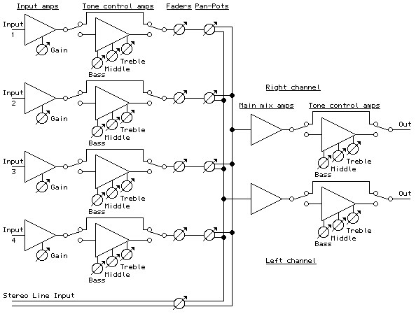
The image below shows a Block diagram of the entire mixer featuring four Input Amplifier Modules followed by four in-out switchable Tone Control Modules, one stereo Line input, four mono Main Faders, one stereo dual-ganged Main Fader, four Pan-Pots, a stereo Main Mixer Amplifier Module and two further Tone Control Modules switchable in and out for each channel, inserted before the main Left and Right outputs.
Obviously this layout can be rearranged at everyone wish.
An astonishing feature of this design lies in the fact that a complete stereo mixer as shown below in the Block diagram draws less than 6mA current!

read more  READ MORE...

4 input mixer schematic

4 input mixer schematic


Portable Mixer

High-quality modular design

9V Battery powered - Very low current drawing

Design description:

The target of this project was the design of a small portable mixer supplied by a 9V PP3 battery, keeping high quality performance.
The mixer is formed assembling three main modules that can be varied in number and/or disposition to suit everyone needs.
The three main modules are:

Input Amplifier Module: a low noise circuit equipped with a variable voltage-gain (10 - 100) pre-set, primarily intended as high quality microphone input, also suitable for low-level line input.

Tone Control Module: a three-band (Bass, Middle, Treble) tone control circuit providing unity-gain when its controls are set to flat frequency response. It can be inserted after one or more Input Amplifier Modules and/or after the Main Mixer Amplifiers.

Main Mixer Amplifier Module: a stereo circuit incorporating two virtual-earth mixers and showing the connection of one Main Fader and one Pan-Pot.

The image below shows a Block diagram of the entire mixer featuring four Input Amplifier Modules followed by four in-out switchable Tone Control Modules, one stereo Line input, four mono Main Faders, one stereo dual-ganged Main Fader, four Pan-Pots, a stereo Main Mixer Amplifier Module and two further Tone Control Modules switchable in and out for each channel, inserted before the main Left and Right outputs.
Obviously this layout can be rearranged at everyone wish.
An astonishing feature of this design lies in the fact that a complete stereo mixer as shown below in the Block diagram draws less than 6mA current!

read more  READ MORE...