Showing posts with label fm transmitter circuit. Show all posts

Circuit diagram 500mW FM PLL transmitter 88-108MHz using LMX3206 – PIC16F870

Circuit diagram 500mW FM PLL transmitter 88-108MHz using LMX3206 – PIC16F870

Circuit diagram 500mW FM PLL transmitter 88-108MHz


500mW PLL FM transmitter 88-108MHz
This PLL transmitter is controlled and the frequency is very stable and can be programmed digitally.
Transmitter will work 88-108 MHz and output power up to 500mW.
With a small change can set the frequency of 50-150 MHz.

The output power is often set to several watts with transistors.
So therefore I decided to build a simple transmitter with great performances.
The frequency of this transmitter can easily be changed by software and space / compress air coil.
This transmitter is the oscillator colpitts. Oscillator is a VCO (voltage controlled oscillator) which is set by the PLL circuit and PIC micro controller.


This oscillator is called the Colpitts oscillator and voltage controlled to achieve the FM (frequency modulation) and PLL control. T1 must be HF transistors to work well, but in this case I use a cheap and common BC817 transistor. LC tank oscillator needs to oscillate properly.
In this case the LC tank consists of L1 with the C1, C2, C3, and varicap BB139.
Coil parallel to the C1 and C2 in series. The same with the varicap and C3.
You may think that L is parallel to the [(C1 / / C2) + (Varicap / / C3)]
C3 will determine the value range VCO. Large value of C3 will be broader in the range VCO can be.

PLL and Microcontroller


Oscillator is made to work as a “Voltage Controlled Oscillator” VCO.
To control the frequency synthesizer circuit LMX 2306 has been added. The PLL circuit has a pickup coil (L2) is connected to pin 6.
This coil should be placed close to the coil L1 to take some of the energy oscillates.
The LMX2306 PLL in to use this frequency to adjust and lock the VCO to the desired frequency.
Systems also need to set the external reference crystal. In this case I use 12.8 MHz.
 pin2 of MX2306 you will find the PLL filter to form a VM that is set voltage of the VCO.
The PLL tries to arrange so that the oscillator frequency Fout kept locked to the desired frequency.
The desired frequency programmed into the PIC EEPROM and clocked into the synthesizer (LMX2306) at power up.
I will below explain how to program the EEPROM to different frequencies.
In the pin14 of your synthesizer control output. In this output you will find a reference frequency for testing.

(I must warn you that the signal is not symmetrical in form. Pulsa positive only a few microseconds, so you will be hard to see on the oscilloscope.) I solved by connecting it to 74HC4020 (14-stage Binary Counter) to input pin 10 Hours. In Q0 (pin 9) you will have a symmetrical square wave with a frequency half since the circuit is a table. In Q1 pin 7 will be divided by 4, see data sheet for more information.

LF input
You want to send audio must be connected to the audio input (left schematic).
Will affect the signal and thus modulate the FM varicap RF carrier frequency.
A potentiometer P1 was added to adjust the depth of modulation (FM Wide or Narrow FM). You may have to play a bit with a value of P1 because it tends to modulate the lot. You may need to add the 500k – 1M potentiometer only. You test and find out for himself.

Buffer stage
Here you find other HF transistors and work in the class C.
Resistor R1 and resistor Re2 regulate the flow of DC. In this case I find that 9.1k will give a good output power and thus equal to 150. If you want to increase the power should be lower Re2. You can add another 150 ohm resistor in parallel.
In the table below I’ll show the output power with different voltages and resistor values of Re2.
I advice you to not run the transmitter with a high output power. Transistor I use is small and tends to be hot.
I advice you to run the unit from the 0 – to 200mW. At the transistor will 500mW pain …* smiles *
At the output you will find a network T. This “filter” will match the transmitter to the antenna impedance output stage.
You have two variables 60pF capacitors to tune the transmitter for best performance.
The antenna I use I a 1 / 4 wave whip antenna (wire) about 75cm long.
Smaller antenna types, but not so good performance as a dipole.
With a dipole you will be more long distance transmitter.
How long can I pass?
It is a very difficult question because the environment affects the transmission distance is very much.
In a city environment with concrete buildings transmitter will send maybe 200m.
I will send a proposed open 2000m.
I did the test and filed with 70mW output power into a “bad” whip antenna is placed in the room I can send 200-300m to a park without a problem. READ MORE...

Circuit diagram 500mW FM PLL transmitter 88-108MHz using LMX3206 – PIC16F870

Circuit diagram 500mW FM PLL transmitter 88-108MHz using LMX3206 – PIC16F870

Circuit diagram 500mW FM PLL transmitter 88-108MHz


500mW PLL FM transmitter 88-108MHz
This PLL transmitter is controlled and the frequency is very stable and can be programmed digitally.
Transmitter will work 88-108 MHz and output power up to 500mW.
With a small change can set the frequency of 50-150 MHz.

The output power is often set to several watts with transistors.
So therefore I decided to build a simple transmitter with great performances.
The frequency of this transmitter can easily be changed by software and space / compress air coil.
This transmitter is the oscillator colpitts. Oscillator is a VCO (voltage controlled oscillator) which is set by the PLL circuit and PIC micro controller.


This oscillator is called the Colpitts oscillator and voltage controlled to achieve the FM (frequency modulation) and PLL control. T1 must be HF transistors to work well, but in this case I use a cheap and common BC817 transistor. LC tank oscillator needs to oscillate properly.
In this case the LC tank consists of L1 with the C1, C2, C3, and varicap BB139.
Coil parallel to the C1 and C2 in series. The same with the varicap and C3.
You may think that L is parallel to the [(C1 / / C2) + (Varicap / / C3)]
C3 will determine the value range VCO. Large value of C3 will be broader in the range VCO can be.

PLL and Microcontroller


Oscillator is made to work as a “Voltage Controlled Oscillator” VCO.
To control the frequency synthesizer circuit LMX 2306 has been added. The PLL circuit has a pickup coil (L2) is connected to pin 6.
This coil should be placed close to the coil L1 to take some of the energy oscillates.
The LMX2306 PLL in to use this frequency to adjust and lock the VCO to the desired frequency.
Systems also need to set the external reference crystal. In this case I use 12.8 MHz.
 pin2 of MX2306 you will find the PLL filter to form a VM that is set voltage of the VCO.
The PLL tries to arrange so that the oscillator frequency Fout kept locked to the desired frequency.
The desired frequency programmed into the PIC EEPROM and clocked into the synthesizer (LMX2306) at power up.
I will below explain how to program the EEPROM to different frequencies.
In the pin14 of your synthesizer control output. In this output you will find a reference frequency for testing.

(I must warn you that the signal is not symmetrical in form. Pulsa positive only a few microseconds, so you will be hard to see on the oscilloscope.) I solved by connecting it to 74HC4020 (14-stage Binary Counter) to input pin 10 Hours. In Q0 (pin 9) you will have a symmetrical square wave with a frequency half since the circuit is a table. In Q1 pin 7 will be divided by 4, see data sheet for more information.

LF input
You want to send audio must be connected to the audio input (left schematic).
Will affect the signal and thus modulate the FM varicap RF carrier frequency.
A potentiometer P1 was added to adjust the depth of modulation (FM Wide or Narrow FM). You may have to play a bit with a value of P1 because it tends to modulate the lot. You may need to add the 500k – 1M potentiometer only. You test and find out for himself.

Buffer stage
Here you find other HF transistors and work in the class C.
Resistor R1 and resistor Re2 regulate the flow of DC. In this case I find that 9.1k will give a good output power and thus equal to 150. If you want to increase the power should be lower Re2. You can add another 150 ohm resistor in parallel.
In the table below I’ll show the output power with different voltages and resistor values of Re2.
I advice you to not run the transmitter with a high output power. Transistor I use is small and tends to be hot.
I advice you to run the unit from the 0 – to 200mW. At the transistor will 500mW pain …* smiles *
At the output you will find a network T. This “filter” will match the transmitter to the antenna impedance output stage.
You have two variables 60pF capacitors to tune the transmitter for best performance.
The antenna I use I a 1 / 4 wave whip antenna (wire) about 75cm long.
Smaller antenna types, but not so good performance as a dipole.
With a dipole you will be more long distance transmitter.
How long can I pass?
It is a very difficult question because the environment affects the transmission distance is very much.
In a city environment with concrete buildings transmitter will send maybe 200m.
I will send a proposed open 2000m.
I did the test and filed with 70mW output power into a “bad” whip antenna is placed in the room I can send 200-300m to a park without a problem. READ MORE...

Understanding FM transmitter circuit

Understanding FM transmitter circuit

Hi,


I'm trying to understand how the following FM transmitter circuit works. I got it from the site

Wireless FM Transmitter. The site has some explanation on how the circuit works, however I'm not sure about a few things, including the electret mic & how the frequency modulation takes place.
The electret microphone has a current of 200uA which changes by +- 3 uA depending on sound waves. This sets the voltage across R1 to 2V and the voltage across the mic to 4 volts. As the sound hits the mic the current through R1 increases slightly reducing the voltage across the mic. Is that what is happening?

This changing voltage is passed on by the coupling cap, C1 to the base of the transistor, which is biased by R2 & R3 to approx 2V. The voltage across R4 with no signal on the mic will be Vb - 0.7 (drop across vbe), 1.3 volts. As the voltage at b changes R4 will change by the same amount. This change in voltage is seen at the base of the tank circuit. And the signals voltage is increased/decreased. Isn't this what happens in AM? As wouldn't the capacitance need to change in order to get Frequency modulation? And if it was amplitude modulation occuring in the FM spectrum, then how would a radio receiver be able to demodulate the signal?

At this point I'm not sure what is happening at the capacitor C3, what is that doing? Is it holding CE at a fixed voltage? And is it along with capacitor C2 considered a bypass capacitor? Or do bypass capacitors need to be connected to ground?
READ MORE...

Understanding FM transmitter circuit

Understanding FM transmitter circuit

Hi,


I'm trying to understand how the following FM transmitter circuit works. I got it from the site

Wireless FM Transmitter. The site has some explanation on how the circuit works, however I'm not sure about a few things, including the electret mic & how the frequency modulation takes place.
The electret microphone has a current of 200uA which changes by +- 3 uA depending on sound waves. This sets the voltage across R1 to 2V and the voltage across the mic to 4 volts. As the sound hits the mic the current through R1 increases slightly reducing the voltage across the mic. Is that what is happening?

This changing voltage is passed on by the coupling cap, C1 to the base of the transistor, which is biased by R2 & R3 to approx 2V. The voltage across R4 with no signal on the mic will be Vb - 0.7 (drop across vbe), 1.3 volts. As the voltage at b changes R4 will change by the same amount. This change in voltage is seen at the base of the tank circuit. And the signals voltage is increased/decreased. Isn't this what happens in AM? As wouldn't the capacitance need to change in order to get Frequency modulation? And if it was amplitude modulation occuring in the FM spectrum, then how would a radio receiver be able to demodulate the signal?

At this point I'm not sure what is happening at the capacitor C3, what is that doing? Is it holding CE at a fixed voltage? And is it along with capacitor C2 considered a bypass capacitor? Or do bypass capacitors need to be connected to ground?
READ MORE...

Two Transistors Wireless Microphone FM Transmitter Circuit Schematic Diagram

Two Transistors Wireless Microphone FM Transmitter Circuit Schematic Diagram

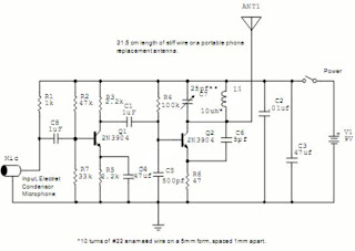
Please be warned if operating this circuit might violate the regulation of your country, because this FM transmitter circuit radiate strong radio frequency to the environment. This wireless microphone is very sensitive, pick up every sound in the 20m radius, and transmit the radio signal up to 2 kilometers in open air. Here is the schematic diagram of the circuit:


The first transistor (Q1) is the pre-amplifier for the microphone, and you can ommit this circuit if you don’t want to transmit the sound picked up by the mic, for example you can can connect your mp3 player directly to C1. The core of this FM transmitter circuit is Q2, a modified Collpits oscillator that the frequency is determined by L1, C4, C6, and the transistor’s internal base-emitter capacitance. The antenna use 1/16 wave length to compromize between the efficiency and the size. If you want the microphone to be less sensitive, you can replace the R1 by a higher resistor, try 10k or 22k, and this might overcome the feedback problem if you use this wireless microphone FM transmitter for a public address system. READ MORE...

Two Transistors Wireless Microphone FM Transmitter Circuit Schematic Diagram

Two Transistors Wireless Microphone FM Transmitter Circuit Schematic Diagram

Please be warned if operating this circuit might violate the regulation of your country, because this FM transmitter circuit radiate strong radio frequency to the environment. This wireless microphone is very sensitive, pick up every sound in the 20m radius, and transmit the radio signal up to 2 kilometers in open air. Here is the schematic diagram of the circuit:


The first transistor (Q1) is the pre-amplifier for the microphone, and you can ommit this circuit if you don’t want to transmit the sound picked up by the mic, for example you can can connect your mp3 player directly to C1. The core of this FM transmitter circuit is Q2, a modified Collpits oscillator that the frequency is determined by L1, C4, C6, and the transistor’s internal base-emitter capacitance. The antenna use 1/16 wave length to compromize between the efficiency and the size. If you want the microphone to be less sensitive, you can replace the R1 by a higher resistor, try 10k or 22k, and this might overcome the feedback problem if you use this wireless microphone FM transmitter for a public address system. READ MORE...

Schematic diagram for the One Transistor FM Radio with Improved Audio Gain

Schematic diagram for the One Transistor FM Radio with Improved Audio Gain


One Transistor FM Radio with improved audio gain.


Some wiring notes:


Unless you have experience with super-regenerative radios, I highly recommend using the FAR Circuits printed circuit board.


Connect the two sections of the variable capacitor (C3) in series to linearize the tuning somewhat. That is, use the connections on either end of C3 and don't use the middle lead.
L2, the RF choke should not be near a ground. The same is true for L1. Capacitance to ground will disturb the feedback.

The gain is just enough to drive an earphone. If you live too far away from radio stations, you might have trouble hearing one. There is no option here for an external antenna (that would require and extra transistor).

You can drive a speaker if you add an external audio amplifier.

If you want a little more audio gain, or you cannot locate a TL431CLP chip, you can use some other audio amplifier in the circuit where pins 1 and 2 of D1 normally connect. You can use an LM386 or a TDA7052 audio amplifier. Quasar DIY project kit #3027 is a complete TDA7052 audio amplifier kit and it works fine in this application.

source : http://www.somerset.net/arm/fm_only_one_transistor_radio.html READ MORE...

Schematic diagram for the One Transistor FM Radio with Improved Audio Gain

Schematic diagram for the One Transistor FM Radio with Improved Audio Gain


One Transistor FM Radio with improved audio gain.


Some wiring notes:


Unless you have experience with super-regenerative radios, I highly recommend using the FAR Circuits printed circuit board.


Connect the two sections of the variable capacitor (C3) in series to linearize the tuning somewhat. That is, use the connections on either end of C3 and don't use the middle lead.
L2, the RF choke should not be near a ground. The same is true for L1. Capacitance to ground will disturb the feedback.

The gain is just enough to drive an earphone. If you live too far away from radio stations, you might have trouble hearing one. There is no option here for an external antenna (that would require and extra transistor).

You can drive a speaker if you add an external audio amplifier.

If you want a little more audio gain, or you cannot locate a TL431CLP chip, you can use some other audio amplifier in the circuit where pins 1 and 2 of D1 normally connect. You can use an LM386 or a TDA7052 audio amplifier. Quasar DIY project kit #3027 is a complete TDA7052 audio amplifier kit and it works fine in this application.

source : http://www.somerset.net/arm/fm_only_one_transistor_radio.html READ MORE...

fm transmitter circuit

fm transmitter circuit

FM Transmitter Circuit
An low power FM Transmitter using an op-amp as the audio preamp and a single transistor as the RF amplifier.

FM Transmitter
Here is the schematic, PC board pattern, and parts placement for a low powered FM transmitter. The range of the transmitter when running at 9V is about 300 feet. Running it from 12V increases the range to about 400 feet. This transmitter should not be used as a room or telephone bug.


FM Transmitter Circuit
This circuit is a simple two transistor (2N2222) fm transmitter

. No license is required for this transmitter according to FCC regulations regarding wireless microphones. If powered by a 9 volt battery and used with an antenna no longer than 12 inches READ MORE...

fm transmitter circuit

fm transmitter circuit

FM Transmitter Circuit
An low power FM Transmitter using an op-amp as the audio preamp and a single transistor as the RF amplifier.

FM Transmitter
Here is the schematic, PC board pattern, and parts placement for a low powered FM transmitter. The range of the transmitter when running at 9V is about 300 feet. Running it from 12V increases the range to about 400 feet. This transmitter should not be used as a room or telephone bug.


FM Transmitter Circuit
This circuit is a simple two transistor (2N2222) fm transmitter

. No license is required for this transmitter according to FCC regulations regarding wireless microphones. If powered by a 9 volt battery and used with an antenna no longer than 12 inches READ MORE...