ne555 datasheet

ne555 datasheet

Description


These devices are monolithic timing circuits capable of producing accurate time delays or oscillation.

In the time delaymode of operation, the timed interval is controlled by a single external resistor and capacit

or network. In the astable mode of operation, the frequency andduty cy clemay beindependently

controlled with two external resistors and asingle external capacitor.
 
 
Features
                                                                                                              Pin Configuration
 
Timing from Micro seconds to Hours                    
 
Astable or Monostable Operation
 
Adjustable Duty Cycle
 
TTL - Compatible Output Can Sink or Source Up to200mA
 
Temperature Stability of0.005%per oC
 
Direct Replacement for Signetics NE555Timer
 
 
                                                                                               Internal Block Digram

  Applications
                                                                        
. Precision timing
. Pulse generation
. Sequential timing
. Timedelay generation
. Pulse width modulation
. Pulse position modulation
. Missing pulse detector


download ne555 datasheet pdf file READ MORE...

ne555 datasheet

ne555 datasheet

Description


These devices are monolithic timing circuits capable of producing accurate time delays or oscillation.

In the time delaymode of operation, the timed interval is controlled by a single external resistor and capacit

or network. In the astable mode of operation, the frequency andduty cy clemay beindependently

controlled with two external resistors and asingle external capacitor.
 
 
Features
                                                                                                              Pin Configuration
 
Timing from Micro seconds to Hours                    
 
Astable or Monostable Operation
 
Adjustable Duty Cycle
 
TTL - Compatible Output Can Sink or Source Up to200mA
 
Temperature Stability of0.005%per oC
 
Direct Replacement for Signetics NE555Timer
 
 
                                                                                               Internal Block Digram

  Applications
                                                                        
. Precision timing
. Pulse generation
. Sequential timing
. Timedelay generation
. Pulse width modulation
. Pulse position modulation
. Missing pulse detector


download ne555 datasheet pdf file READ MORE...

Understanding Diagram Listrik Electrical Schema

In engineering design activities, maintenance or troubleshooting, it is essential for an engineer or technician, whether it's personnel in the field of electricity or in other fields (electronics and telecommunications) in order to understand or control of the circuit diagram. Circuit diagram is a picture or instructions on what components are in an electrical circuit, functions and relationships between series, so expect when an engineer or technician to understand about tesebut the circuit diagram, they would be more appropriate in designing or analyzing a series of disturbances to a circuit. In general, the circuit diagram divided into four types, namely:Schematic diagram


Schematic diagram is a drawing technique that describes a circuit using an electric symbol symbol. Schematic diagram of the electrical symbol symbol is associated with a line describing the connections and relationships of electrical components in the circuit. By using Schematic diagram, the workings of an electrical system can be observed from input to output
READ MORE...

BATTERY CHARGER SCHEMATIC

BATTERY CHARGER SCHEMATIC

High Efficiency Battery Charger using Power components ... Battery Charger. The complete schematic for a 12 V/15 V battery ... Figure 3. High-efficiency battery charger schematic. page 3 of 4. Efficiency Estimation ...

DOWNLOAD
http://cdn.vicorpower.com/documents/design_articles/pb_battery-charger.pdf

High Efficiency Battery Charger using Power componentS ... Battery Charger. The complete schematic for a 12V/15V battery ... Figure 3. High-efficiency battery charger schematic. page 3 of 4. Efficiency Estimation ...

DOWNLOAD
http://www.ur-group.co.uk/vicor/pdfs/power/pb_battery-charger.pdf

Smart Battery Charger Evaluation Kit User's Manual The Smart Battery Charger Evaluation Board schematic diagram and other related drawings are ... When a battery is connected to the charger and the Z8 enables ...
DOWNLOAD
http://www.zilog.com/docs/z8/battery_charger/ch3_hw.pdf

Battery Charging (PDF) 3A Battery Charger with Logic-level Controls ... Figure 7 shows the schematic of a battery charger that was designed to recharge the Li ...

DOWNLOAD
http://www.national.com/appinfo/power/files/f7.pdf

Battery charger using the ST6-REALIZER inflection points can be implemented with this battery charger ST6 board. HARDWARE SCHEMATICS ... 2/14. Figure 1 : Simple Battery Charger Circuit Schematic ...

DOWNLOAD
http://www.st.com/stonline/products/literature/an/2527.pdf READ MORE...

BATTERY CHARGER SCHEMATIC

BATTERY CHARGER SCHEMATIC

High Efficiency Battery Charger using Power components ... Battery Charger. The complete schematic for a 12 V/15 V battery ... Figure 3. High-efficiency battery charger schematic. page 3 of 4. Efficiency Estimation ...

DOWNLOAD
http://cdn.vicorpower.com/documents/design_articles/pb_battery-charger.pdf

High Efficiency Battery Charger using Power componentS ... Battery Charger. The complete schematic for a 12V/15V battery ... Figure 3. High-efficiency battery charger schematic. page 3 of 4. Efficiency Estimation ...

DOWNLOAD
http://www.ur-group.co.uk/vicor/pdfs/power/pb_battery-charger.pdf

Smart Battery Charger Evaluation Kit User's Manual The Smart Battery Charger Evaluation Board schematic diagram and other related drawings are ... When a battery is connected to the charger and the Z8 enables ...
DOWNLOAD
http://www.zilog.com/docs/z8/battery_charger/ch3_hw.pdf

Battery Charging (PDF) 3A Battery Charger with Logic-level Controls ... Figure 7 shows the schematic of a battery charger that was designed to recharge the Li ...

DOWNLOAD
http://www.national.com/appinfo/power/files/f7.pdf

Battery charger using the ST6-REALIZER inflection points can be implemented with this battery charger ST6 board. HARDWARE SCHEMATICS ... 2/14. Figure 1 : Simple Battery Charger Circuit Schematic ...

DOWNLOAD
http://www.st.com/stonline/products/literature/an/2527.pdf READ MORE...

Electricity Tutorial

This tutorial is a brief introduction to the concepts of charge, voltage, and current. This tutorial is not as long and tedious as a college textbook, yet it contains more information than students are likely to find in an elementary schoolbook.
The Atom

A drawing of an atomOn the left is a conceptual drawing of an atom. Atoms are the building blocks of matter. Everything is made of atoms, from rocks, to trees, to stars, to even yourself. An atom consists of a tightly packed nucleus containing one or more protons (colored red in the picture), and usually an equal number of neutrons (gray). Electrons (blue) surround the nucleus, forming an electron cloud. The number of electrons in an electrically stable atom is always equal to the number of protons in the nucleus.


Electric Charge

Opposite charges attract. Like charges repel. A curious thing happens between protons and electrons: a proton and an electron are always attracted to one another, while a proton will repel other protons, and an electron will repel other electrons. This behavior is caused by something called the electric force. Protons are said to have a positive electric charge, while electrons have a negative electric charge. Two objects with the same type of charge push away from each other, while two objects with opposite charges attract to each other. Since a proton and an electron have opposite electric charges, they are attracted to each other. Two protons, however, move away from each other because of their equal electric charges. The same is true of two electrons, which push away from each other because of their equal negative charges.
Electric Balance

Electric balance Most matter contains an equal number of protons and electrons. The negative electrons balance out the positive protons, and the matter has no overall electrical charge. The word overall is important, since the charges are still there, bouncing around inside the matter. Electrical charges are everywhere, but we just can't sense them because they are in balance. In fact, if you take chemistry, you'll learn that the electric force is the very thing that holds matter together. The next time you pick something up, just think that whatever you are holding is literally filled with electric charge. This is an important fact that many people miss when they study electricity.
Static Electricity

A drawing of two ions Let's say we steal an electron from one atom and give the electron to another atom. One atom will have an overall positive charge and the other will have an overall negative charge. When this happens, the two atoms are called ions. Because ions have an overall electric charge, they can interact with other charged objects. Since like charges repel and opposite charges attract, a positive ion will attract negatively charged objects, such as electrons or other ions, and will repel positively charged objects. A negatively charged ion will attract positively charged objects, and will repel other negatively charged objects.

The same is true for larger objects. If you take electrons from one object and place them on another object, the first object will have an overall positive charge while the second will have an overall negative charge. Depending on the types of objects and the amount of charge involved, the electric force may be enough to cause the objects to stick together. This phenomenon is often referred to as "static electricity."

There are several ways to steal electrons from one object and give them to another. Some of the ways include chemical reactions, mechanical motion, light, and even heat. If you rub a glass rod with silk, the electrons in the glass rod will be knocked off and collected on the silk. The glass rod gains an overall positive charge, and the silk gains an overall negative charge. In a battery, chemical reactions are used to force electrons from the positive terminal and place them on the negative terminal.
Measuring Charges

The amount of overall electric charge possessed by an object is measured in coulombs. One coulomb is roughly equal to the amount of charge possessed by 6,000,000,000,000,000,000 (six billion billion) electrons. While this may seem like a huge number at first, it is not really that much, since electrons are so tiny. Just to give you an idea, one coulomb is roughly the amount of charge that flows through a 12-watt automotive light bulb in one second.

If the amount of charge possessed by two objects and the distance between them are known, it is possible to calculate the amount of force between the objects using a formula known as Coulomb's law. This law was discovered by Charles Augustin de Coulomb in 1784, and states that the force between two charged objects varies directly as the charges of the objects and inversely as the square of the distance between them. Coulomb's law is given below in formula form:

F=kqq'/r^2
F is the force, in Newtons.
q and q' are the charges of the two objects, in coulombs.
r is the distance between the objects, in meters.
k is a constant equal to 8.98755×10⁹ N m2 C-2
Voltage

Whenever electrons are taken from one object and placed on another object, causing an imbalance of charge, we say that a voltage exists. That is what somebody means when they say that something has so many volts of electricity. They are describing a difference of charge in two different places. A standard AA battery has a difference of 1.5 volts between its positive and negative terminal, while car battery has a difference of 12 volts between its two terminals, and the everyday type of static electricity that causes things to stick together and occasionally gives you a jolt when you touch a metal object is usually measured in thousands of volts.

Two parallel charged plates.Another way to understand voltage is to think of an "electric field." Imagine a plate with positive charge next to a plate with negative charge. If I place a positive charge between these plates, the plates’ electric field will attract the charge to the negative side. Imagine that I place a 1 coulomb positive charge next to the negative plate, and then pull it towards the positive plate. Because the electric field creates a force in the opposite direction, moving the charge requires energy. The amount of energy depends on the distance between the plates and the strength of the electric field created by the plates. We call this energy the electric field’s "voltage." One volt is the amount of energy in joules required to move 1 coulomb of charge through an electric field. Mathematically, 1Volt = 1Joule / 1Coulomb.

Volts are useful, because they neatly describe the size and strength of any electric field. Visualizing the electric field between two simple plates is easy, but visualizing the field in a complicated circuit with batteries, motors, light bulbs, and switches is very difficult. Voltage simplifies circuits like these by describing the entire electric field with a single number.
Electric Current

Current in motion animaiton. The word current comes from the Latin word currere, which means to run or to flow. An electric current is nothing more than the flow of electric charges. Electric charges can only flow through certain materials, called conductors. Although the electrons in most materials are confined to fixed orbits, some materials, including most metals, have many loose electrons which are free to wander around through the material. Materials with this property act as conductors. When a conductor is placed between two charged objects, these loose electrons are pushed away by the negatively charged object and are sucked into the positively charged object. The result is that there is a flow of charge, called a current, and the two object's charges become balanced. The amount of current flowing through a conductor at any given time in measured in amperes, or amps for short. When you read that something uses so many amps, what you are being told is the amount of current flowing through the device. One ampere is equal to the flow of one coulomb of charge in one second.
Batteries and Current

Batteries and current In the previous paragraph, we looked at how current flows from one charged object to another, canceling out the charges of the two objects. Once the charges were canceled, the current stopped. If current were always this short-lived, it would be very impractical. Imagine a flashlight that only lasted a fraction of a second before needing to be recharged! While current does tend to cancel out charges on two objects and then stop flowing, if a charge can be placed on the objects faster than the current can drain the charge, it is possible to keep a current flowing indefinitely. That is what happens in a battery. Chemical reactions within the battery pump electrons from the positive terminal to the negative terminal faster than the device connected to the battery can drain them. The battery will continue to supply as much current as the device requires until the chemicals within the battery are used up, at which point the battery is dead and must be replaced.
Resistance

All conductors offer some degree of resistance to the flow of electric current. What happens is this: As electrons travel through the conductor, they bump into atoms, losing some of their movement in jiggling the atom. The result is that the current flowing through the conductor is slowed down, and the conductor is heated. The amount that a given conductor resists the flow of electric current is measured in ohms.
Power

Whenever current flows, work is done. A conductor may be heated, a motor may be spun, a bulb might give off light, or some other form of energy may be released. There is a simple law that tells exactly how much work may be done by a flowing current. The amount of work done is equal to the voltage of the supply times the current flowing through the wire. This law is expressed in the form P=IV, where P is the power in watts, I is the current in amps, and V is the voltage in volts. For example, if we find that a light bulb draws half of an amp at 120 volts, we simply multiply the 120 volts by half an amp to find that the bulb draws 60 watts of power.
Ohm's Law

V=IR Let's say you have a six volt battery and you need to draw two amps of current. What resistance should you make the conductor? Or let's say you have a three volt power supply and a thousand ohm resistor. How much current would flow through the resistor if you were to connect the resistor to the power supply? In order to find the answers to these questions, all you need to do is to use a simple mathematical formula called ohm's law. Ohm's law states that the amount of current flowing through a conductor times the resistance of the conductor is equal to voltage of the power supply. This law is often expressed in the form V=IR, where V is the voltage measured in volts, I is the current measured in amps, and R is the resistance measured in ohms.


electric circuit, unbroken path along which an electric current exists or is intended or able to flow. A simple circuit might consist of an electric cell (the power source), two conducting wires (one end of each being attached to each terminal of the cell), and a small lamp (the load) to which the free ends of the wires leading from the cell are attached. When the connections are made properly, current flows, the circuit is said to be “closed,” and the lamp will light. The current flows from the cell along one wire to the lamp, through the lamp, and along the other wire back to the cell. When the wires are disconnected, the circuit is said to be “open” or “broken.” In practice, circuits are opened by such devices as switches, fuses, and circuit breakers (see fuse, electric; circuit breaker; short circuit). Two general circuit classifications are series and parallel. The elements of a series circuit are connected end to end; the same current flows through its parts one after another. The elements of a parallel circuit are connected so that each component has the same voltage across its terminals; the current flow is divided among its parts. When two circuit elements are connected in series, their effective resistance (impedance if the circuit is being fed alternating current) is equal to the sum of the separate resistances; the current is the same in each component throughout the circuit. When circuit elements are connected in parallel, the total resistance is less than that of the element having the least resistance, and the total current is equal to the sum of the currents in the individual branches. A battery-powered circuit is an example of a direct-current circuit; the voltages and currents are constant in magnitude and do not vary with time. In alternating-current circuits, the voltage and current periodically reverse direction with time. A standard electrical outlet supplies alternating current. Lighting circuits and electrical machinery use alternating current circuits. Many other devices, including computers, stereo systems, and television sets, must first convert the alternating current to direct current. That is done by a special internal circuit usually called a power supply. A digital circuit is a special kind of electronic circuit used in computers and many other devices. Magnetic circuits are analogous to electric circuits, where magnetic materials are regarded as conductors of magnetic flux. Magnetic circuits can be part of an electric circuit; a transformer is an example. Equivalent circuits are used in circuit analysis as a modeling tool; a simple circuit made up of a resistor, and an inductor might be used to electrically represent a loudspeaker. Electrical circuits can also be used in other fields of studies. In the study of heat flow, for example, a resistor is used to represent thermal insulation. Operating electric circuits can be used for general problem solving (as in an analog computer).
Kirchhoff's laws


Kirchhoff's laws [for Gustav R. Kirchhoff], pair of laws stating general restrictions on the current and voltage in an electric circuit. The first of these states that at any given instant the sum of the voltages around any closed path, or loop, in the network is zero. The second states that at any junction of paths, or node, in a network the sum of the currents arriving at any instant is equal to the sum of the currents flowing away.


inductance


inductance, quantity that measures the electromagnetic induction of an electric circuit component; it is a property of the component itself rather than of the circuit as a whole. The self-inductance, L, of a circuit component determines the magnitude of the electromagnetic force (emf) induced in it as a result of a given rate of change of the current through the component. Similarly, the mutual inductance, M, of two components, one in each of two separate but closely located circuits, determines the emf that each may induce in the other for a given current change. Inductance is expressed in henrys (for Joseph Henry). An inductor is a device designed to produce an inductance, e.g., a coil; an ideal inductor, i.e., one having no resistance or capacitance (see impedance), is often called an inductance.
Hukum Ohm menyatakan bahwa besar arus yang mengalir pada suatu konduktor pada suhu tetap sebanding dengan beda potensial antara kedua ujung-ujung konduktor

I = V / R


HUKUM OHM UNTUK RANGKAIAN TERTUTUP


I = n E
R + n rd

I = n
R + rd/p

n = banyak elemen yang disusun seri
E = ggl (volt)
rd = hambatan dalam elemen
R = hambatan luar
p = banyaknya elemen yang disusun paralel

RANGKAIAN HAMBATAN DISUSUN SERI DAN PARALEL

SERI

R = R1 + R2 + R3 + ...
V = V1 + V2 + V3 + ...
I = I1 = I2 = I3 = ...


PARALEL

1 = 1 + 1 + 1
R R1 R2 R3

V = V1 = V2 = V3 = ...
I = I1 + I2 + I3 + ...


ENERGI DAN DAYA LISTRIK

ENERGI LISTRIK (W)
adalah energi yang dipakai (terserap) oleh hambatan R.

W = V I t = V²t/R = I²Rt


Joule = Watt.detik
KWH = Kilo.Watt.jam

DAYA LISTRIK (P) adalah energi listrik yang terpakai setiap detik.

P = W/t = V I = V²/R = I²R


HUKUM KIRCHOFF I : jumlah arus menuju suatu titik cabang sama dengan jumlah arus yang meninggalkannya.


S Iin = Iout

HUKUM KIRCHOFF II : dalam rangkaian tertutup, jumlah aljabar GGL (e) dan jumlah penurunan potensial sama dengan nol.


Se = S IR = 0

ALAT UKUR LISTRIK TERDIRI DARI

1. JEMBATAN WHEATSTONE


digunakan untuk mengukur nilai suatu hambatan dengan cara mengusahakan arus yang mengalir pada galvanometer = nol (karena potensial di ujung-ujung galvanometer sama besar). Jadi berlaku rumus perkalian silang hambatan :

R1 R3 = R2 Rx
2. AMPERMETER


untuk memperbesar batas ukur ampermeter dapat digunakan hambatan Shunt (Rs) yang dipasang sejajar/paralel pada suatu rangkaian.

Rs = rd 1/(n-1)
n = pembesaran pengukuran
3. VOLTMETER


untuk memperbesar batas ukur voltmeter dapat digunakan hambatan multiplier (R-) yang dipasang seri pada suatu rangkaian. Dalam hal ini R. harus dipasang di depan voltmeter dipandang dari datangnya arus listrik.

Rm = (n-1) rd
n = pembesaran pengukuran

TEGANGAN JEPIT (V.b) :
adalah beda potensial antara kutub-kutub sumber atau antara dua titik yang diukur.

1. Bila batere mengalirkan arus maka tegangan jepitnya adalah:
Vab = e - I rd


2. Bila batere menerima arus maka tegangan jepitnya adalah:
Vab = e + I rd


3. Bila batere tidak mengalirkan atau tidak menerima arus maka
tegangan jepitnya adalah .
Vab = e


Dalam menyelesaian soal rangkaian listrik, perlu diperhatikan :

1. Hambatan R yang dialiri arus listrik. Hambatan R diabaikan jika tidak
dilalui arus listrik.

2. Hambatan R umumnya tetap, sehingga lebih cepat menggunakan
rumus yang berhubungan dengan hambatan R tersebut.

3. Rumus yang sering digunakan: hukum Ohm, hukum Kirchoff, sifat
rangkaian, energi dan daya listrik.

Contoh 1 :

Untuk rangkaian seperti pada gambar, bila saklar S1 dan S2 ditutup maka hitunglah penunjukkan jarum voltmeter !

Jawab :

Karena saklar S1 dan S2 ditutup maka R1, R2, dan R3 dilalui arus listrik, sehingga :
1 = 1 + 1
Rp R2 R3

Rp = R2 R3 = 2W
R2 + R1
V = I R = I (R1 + Rp)

I = 24/(3+2) = 4.8 A


Voltmeter mengukur tegangan di R2 di R3, dan di gabungkan R2 // R3, jadi :

V = I2 R2 = I3 R3 = I Rp
V = I Rp = 0,8 V

Contoh 2:

Pada lampu A dan B masing-masing tertulis 100 watt, 100 volt. Mula-mula lampu A den B dihubungkan seri dan dipasang pada tegangan 100 volt, kemudian kedua lampu dihubungkan paralel dan dipasang pada tegangan 100 volt. Tentukan perbandingan daya yang dipakai pada hubungan paralel terhadap seri !
Hambatan lampu dapat dihitung dari data yang tertulis dilampu :
RA = RB = V²/P = 100²/100 = 100 W

Untuk lampu seri : RS = RA + RB = 200 W
Untuk lampu paralel : Rp = RA × RB = 50 W
RA + RB

Karena tegangan yang terpasang pada masing-masing rangkaian sama maka gunakan rumus : P = V²/R

Jadi perbandingan daya paralel terhadap seri adalah :
Pp = V² : V² = Rs = 4
Ps Rp Rs Rp 1

Contoh 3:

Dua buah batere ujung-ujungnya yang sejenis dihubungkan, sehingga membentuik hubungan paralel. Masing-masing batere memiliki GGL 1,5 V; 0,3 ohm dan 1 V; 0,3 ohm.Hitunglah tegangan bersama kedua batere tersebut !

Jawab :

Tentakan arah loop dan arah arus listrik (lihat gambar), dan terapkan hukum Kirchoff II,
Se + S I R = 0
e1 + e2 = I (r1 + r2)

I = (1,5 - 1) = 5 A
0,3 + 0,3 6


Tegangan bersama kedua batere adalah tegangan jepit a - b, jadi :

Vab = e1 - I r1 = 1,5 - 0,3 5/6 = 1,25 V

1= e2 + I R2 = 1 + 0,3 5/6 = 1,25 V

Contoh 4:

Sebuah sumber dengan ggl = E den hambatan dalam r dihubungkan ke sebuah potensiometer yang hambatannya R. Buktikan bahwa daya disipasi pada potensiometer mencapai maksimum jika R = r.

Jawab :
Dari Hukum Ohm : I = V/R = e
R+r

Daya disipasi pada R : P = I²R = e ²R
(R+r)²

Agar P maks maka turunan pertama dari P harus nol: dP/dR = 0 (diferensial parsial)

Jadi e² (R+r)² - E² R.2(R+r) = 0
(R+r)4
e² (R+r)² = e² 2R (R+r) Þ R + r = 2R
R = r (terbukti)

ARUS/TEGANGAN BOLAK-BALIK

Arus/tegangan bolak-balik adalah arus/tegangan yang besarnya selalu berubah-ubah secara periodik. Simbol tegangan bolak-balik adalah ~ dan dapat diukur dengan Osiloskop (mengukur tegangan maksimumnya).


NILAI EFEKTIF KUAT ARUS/TEGANGAN AC

Nilai efektif kuat arus/tegangan AC adalah arus/tegangan AC yang dianggap setara dengan kuat arus/tegangan AC yang menghasilkan jumlah kalor yang sama ketika melalui suatu penghantar dalam waktu yang sama.

Kuat arus efektif : Ief = Imaks / Ö2

Tegangan efektif : Vef = Vmaks / Ö2

Besaran yang ditunjukkan oleh voltmeter/amperemeter DC adalah tegangan/kuat arus DC yang sesungguhnya,sedangkan yang ditunjukan oleh voltmeter/amperemeter AC adalah tegangan/kuat arus efektif, bukan tegangan/kuat arus sesungguhnya.
READ MORE...

How to Use a FM Transmitter to Listen to Internet Radio

How to Use a FM Transmitter to Listen to Internet Radio

Gone are the good old days of Internet radio when you had to stay chained to your desktop PC to enjoy the music. The FM transmitter takes any audio coming from a computer and transmits it to a FM radio, allowing you to use your FM radios as speakers.

Now you can wander through the house listening to your favorite songs.

Decide which type of FM radio transmitter is best for you. There are several types on the market that differ in size, transmission distance, power supply method, number of FM transmitter frequencies, portability and price.


Purchase a FM transmitter. You can buy them online or at a local electronics retailer.Such as http://www.papatek.com/Cell%2DPhone%2DAccessories

Connect the FM transmitter to its power source and then to your PC. Read the manufacturer's instructions for your model. Depending on the type of FM transmitter you buy, it may be powered by batteries, computer USB port or AC power. Most models come with the necessary connection cables. A FM transmitter USB simply plugs into a USB port of any computer
 http://www.papatek.com/Cell-Phone-Accessories/Blue-LED-F ...


Locate an available FM frequency on the dial of your FM radio. The manufacturer's instructions will list the frequencies that are available with the FM transmitter. It is not uncommon that you will probably need to try more than one of the listed frequencies before you find one that works.

Listen and enjoy your favorite Internet radio music or program with the freedom to move around. http://www.papatek.com/Cell-Phone-Accessories/FM-Transmitter-Hands-free-Car-Kit-For-Blackberry-Phone.html READ MORE...

How to Use a FM Transmitter to Listen to Internet Radio

How to Use a FM Transmitter to Listen to Internet Radio

Gone are the good old days of Internet radio when you had to stay chained to your desktop PC to enjoy the music. The FM transmitter takes any audio coming from a computer and transmits it to a FM radio, allowing you to use your FM radios as speakers.

Now you can wander through the house listening to your favorite songs.

Decide which type of FM radio transmitter is best for you. There are several types on the market that differ in size, transmission distance, power supply method, number of FM transmitter frequencies, portability and price.


Purchase a FM transmitter. You can buy them online or at a local electronics retailer.Such as http://www.papatek.com/Cell%2DPhone%2DAccessories

Connect the FM transmitter to its power source and then to your PC. Read the manufacturer's instructions for your model. Depending on the type of FM transmitter you buy, it may be powered by batteries, computer USB port or AC power. Most models come with the necessary connection cables. A FM transmitter USB simply plugs into a USB port of any computer
 http://www.papatek.com/Cell-Phone-Accessories/Blue-LED-F ...


Locate an available FM frequency on the dial of your FM radio. The manufacturer's instructions will list the frequencies that are available with the FM transmitter. It is not uncommon that you will probably need to try more than one of the listed frequencies before you find one that works.

Listen and enjoy your favorite Internet radio music or program with the freedom to move around. http://www.papatek.com/Cell-Phone-Accessories/FM-Transmitter-Hands-free-Car-Kit-For-Blackberry-Phone.html READ MORE...

Broadband Colpitts VCO for TV Tuner

Broadband Colpitts VCO for TV Tuner


The high performance of modern set-top DBS TV tuners require broadband voltage control oscillator (VCO) designs at a competitive cost. To realize these goals, design engineers are challenged to create high performance, low-cost VCOs.

The traditional design of Colpitts oscillator is used for many VCO applications. Designing a broadband Colpitts oscillator with coverage from 1–2 GHz requires the selection and interaction of an appropriate varactor diode for its resonator. This design describes a broadband Colpitts VCO that incorporates the SMV1265-011 varactor diode.


Broadband Colpitts Variable Controll Oscillator 1-2 GHz Schematic


Broadband Colpitts Variable Controll Oscillator 1-2 GHz PCB Layout


This varactor diode was specifically developed at Alpha for this application. The VCO design, based on Libra Series IV simulation, shows good correlation between measured and simulated performance. This application note includes a board layout and materials list.


More info: A Colpitts VCO for Wideband (0.95–2.15 GHz) Set-Top TV Tuner Applications
 
http://www.ziddu.com/download/9053779/1-2ghzvco.pdf.html READ MORE...

Broadband Colpitts VCO for TV Tuner

Broadband Colpitts VCO for TV Tuner


The high performance of modern set-top DBS TV tuners require broadband voltage control oscillator (VCO) designs at a competitive cost. To realize these goals, design engineers are challenged to create high performance, low-cost VCOs.

The traditional design of Colpitts oscillator is used for many VCO applications. Designing a broadband Colpitts oscillator with coverage from 1–2 GHz requires the selection and interaction of an appropriate varactor diode for its resonator. This design describes a broadband Colpitts VCO that incorporates the SMV1265-011 varactor diode.


Broadband Colpitts Variable Controll Oscillator 1-2 GHz Schematic


Broadband Colpitts Variable Controll Oscillator 1-2 GHz PCB Layout


This varactor diode was specifically developed at Alpha for this application. The VCO design, based on Libra Series IV simulation, shows good correlation between measured and simulated performance. This application note includes a board layout and materials list.


More info: A Colpitts VCO for Wideband (0.95–2.15 GHz) Set-Top TV Tuner Applications
 
http://www.ziddu.com/download/9053779/1-2ghzvco.pdf.html READ MORE...

VGA to TV Converter Circuit

VGA to TV Converter Circuit

This converter circuit basically takes VGA signals and converts it to RGB + composite sync signal which can be fed to TV via SCART connector. VGA card picture components RED, GREEN and BLUE are already at the correct voltage level (0.7Vpp) and has correct impedance (75 ohm) for direct connection to correspondign inputs in the TV.


VGA to TV Converter Ciruit


VGA to TV Converter Printed Circuit Board (PCB)


For combining separate horizonal and vertical sync signal from VGA card to one composite sync signal needs a sync signal conversion which is feed to TV video in pin in SCART connector. The tv converter circuit has also sends correct level signal to the TV RGB input enabling control pin in the SCART connector (pin 16).


The circuit is simply based on one TTL chip with four XOR ports, two resistors and two capacitors. TTL chip was logical choise because VGA sync signals are TTL level signals.


The sync signal combiner has a system to adjust to different sync polarities so that it always makes correct composite sync signals. VGA card uses different sync signal polarities to tell the monitor which resolution is used. This circuit adjusts to sync signal polarity changes in less than 200 milliseconds, which is faster than setting time of a normal VGA monitor in the display mode change. The tv converter circuit needs well regulates +5V (+/-5%) power supply and takes about 120 mA current.


VGA to TV converter parts list are as follow:


Main circuit

U1 74LS86 (74HC86 or 74HCT86 can also be used)

C1 22 microfarads 16V electrolytic capacitor

C2 use 47 uF 16V electrolytic for more reliable operation (22 uF listed schematic can cause problems in some cases)

R1,R2 2.2 kohm, 1/4 W

R3,R4,R5 2.2 kohm, 1/4 W

R6,R7,R9 47 ohm, 1/2 W

R8 120 ohm, 1/2 W

T1,T2 BC547B (2N2222 should also work but note the different pinout)

P1 15 pin SUB-D connector (DE-15)


Output connector

21 pin EURO/SCART connector

Wiring:

Red, Green, Blue and Composite Sync lines should be wired using 75 ohm coaxial cable for best picture quality, but can be replaced with normal shielded wire.


Power supply components

7805 regulator chip

100 uF electrolytic 25V

10 uF electrolytic 16V

100 nF polyester or ceramic condensator

Wall adapter which outputs 8-18V DC and 150 mA or more current

Connector for connecting wall adaptor to circuit


Source: http://www.tkk.fi/Misc/Electronics/circuits/vga2tv/circuit.html READ MORE...

VGA to TV Converter Circuit

VGA to TV Converter Circuit

This converter circuit basically takes VGA signals and converts it to RGB + composite sync signal which can be fed to TV via SCART connector. VGA card picture components RED, GREEN and BLUE are already at the correct voltage level (0.7Vpp) and has correct impedance (75 ohm) for direct connection to correspondign inputs in the TV.


VGA to TV Converter Ciruit


VGA to TV Converter Printed Circuit Board (PCB)


For combining separate horizonal and vertical sync signal from VGA card to one composite sync signal needs a sync signal conversion which is feed to TV video in pin in SCART connector. The tv converter circuit has also sends correct level signal to the TV RGB input enabling control pin in the SCART connector (pin 16).


The circuit is simply based on one TTL chip with four XOR ports, two resistors and two capacitors. TTL chip was logical choise because VGA sync signals are TTL level signals.


The sync signal combiner has a system to adjust to different sync polarities so that it always makes correct composite sync signals. VGA card uses different sync signal polarities to tell the monitor which resolution is used. This circuit adjusts to sync signal polarity changes in less than 200 milliseconds, which is faster than setting time of a normal VGA monitor in the display mode change. The tv converter circuit needs well regulates +5V (+/-5%) power supply and takes about 120 mA current.


VGA to TV converter parts list are as follow:


Main circuit

U1 74LS86 (74HC86 or 74HCT86 can also be used)

C1 22 microfarads 16V electrolytic capacitor

C2 use 47 uF 16V electrolytic for more reliable operation (22 uF listed schematic can cause problems in some cases)

R1,R2 2.2 kohm, 1/4 W

R3,R4,R5 2.2 kohm, 1/4 W

R6,R7,R9 47 ohm, 1/2 W

R8 120 ohm, 1/2 W

T1,T2 BC547B (2N2222 should also work but note the different pinout)

P1 15 pin SUB-D connector (DE-15)


Output connector

21 pin EURO/SCART connector

Wiring:

Red, Green, Blue and Composite Sync lines should be wired using 75 ohm coaxial cable for best picture quality, but can be replaced with normal shielded wire.


Power supply components

7805 regulator chip

100 uF electrolytic 25V

10 uF electrolytic 16V

100 nF polyester or ceramic condensator

Wall adapter which outputs 8-18V DC and 150 mA or more current

Connector for connecting wall adaptor to circuit


Source: http://www.tkk.fi/Misc/Electronics/circuits/vga2tv/circuit.html READ MORE...

Simple High efficiency Inverter Circuits

Simple High efficiency Inverter Circuits

Description


1. Field of the InventionThis invention relates generally to the field of electrical energy conversion systems and more particularly to push-pull inverter circuits utilizing a solid state active element oscillator of the multivibrator type to convert an input DC voltageto a high frequency AC output voltage.2. Description of the Prior ArtPush-pull inverter circuits are generally recognized as the most efficient type for converting DC voltage into an AC output voltage. Such circuits typically include a source of DC potential, an output transformer, and a pair of switchingtransistors connected to control the flow of current through the output transformer for thereby producing an AC voltage output across the transformer. Efficient conversion of the DC voltage into the AC output voltage requires that the conduction of theswitching transistors be precisely controlled. Such precise control can serve to minimize undesirable energy losses within the circuit itself. Some of the causes of such energy losses have been recognized and are generally regarded as inherent in suchcircuits, or in the components making up such circuits. Some of these losses are:1. Common-mode conduction which occurs when both of the switching transistors conduct simultaneously. This loss is usually related to the inherent and generally unavoidable delay associated with the turn-off action of the conducting transistor,coupled with the fact that there generally is no corresponding delay associated with the turning on of the other transistor.2. Turn-off transition loss which is due to the power dissipation that occurs within each transistor during its turn-off transition. To minimize this loss, it is necessary to operate each transistor near its maximum switching speed capability. This in turn requires that the charge carriers stored at the transistor base-emitter junction be evacuated as rapidly as possible.It is also more important to prevent the collector voltage from rising significantly be

download now READ MORE...

Simple High efficiency Inverter Circuits

Simple High efficiency Inverter Circuits

Description


1. Field of the InventionThis invention relates generally to the field of electrical energy conversion systems and more particularly to push-pull inverter circuits utilizing a solid state active element oscillator of the multivibrator type to convert an input DC voltageto a high frequency AC output voltage.2. Description of the Prior ArtPush-pull inverter circuits are generally recognized as the most efficient type for converting DC voltage into an AC output voltage. Such circuits typically include a source of DC potential, an output transformer, and a pair of switchingtransistors connected to control the flow of current through the output transformer for thereby producing an AC voltage output across the transformer. Efficient conversion of the DC voltage into the AC output voltage requires that the conduction of theswitching transistors be precisely controlled. Such precise control can serve to minimize undesirable energy losses within the circuit itself. Some of the causes of such energy losses have been recognized and are generally regarded as inherent in suchcircuits, or in the components making up such circuits. Some of these losses are:1. Common-mode conduction which occurs when both of the switching transistors conduct simultaneously. This loss is usually related to the inherent and generally unavoidable delay associated with the turn-off action of the conducting transistor,coupled with the fact that there generally is no corresponding delay associated with the turning on of the other transistor.2. Turn-off transition loss which is due to the power dissipation that occurs within each transistor during its turn-off transition. To minimize this loss, it is necessary to operate each transistor near its maximum switching speed capability. This in turn requires that the charge carriers stored at the transistor base-emitter junction be evacuated as rapidly as possible.It is also more important to prevent the collector voltage from rising significantly be

download now READ MORE...

AM FM Antenna Booster


This antenna booster circuit can be used to amplify the weak signal received by the antenna. Antenna for AM/FM is usually not tuned for the optimal dimension of 1/4 wavelength, since we prefer small portable size. This untuned antenna has very low gain, so the antenna booster circuit here is very helpful in getting better signal reception. Here is the schematic diagram of the circuit:

Use around 470uH coil for L1 if you use for AM frequency (700kHz-1.5MHz) and use around 20uH for SW or FM receiver. For short wave performance, using this antenna booster, you’ll get a strong signal as we get from a 20-30 feet antenna, with only a standard 18″ telescopic antenna and this booster circuit. The power supply should be bypassed by a 47nF capacitor to ground, at a point that should be chosen as close as possible to L1.
READ MORE...

UHF Antenna Booster

UHF Antenna Booster

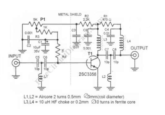
UHF antenna booster can be used for better reception, especially when you’re far from TV station / relay transmitter. This UHF antenna booster works in 400-850 MHz range. Here is the circuit diagram of the UHF antenna booster:


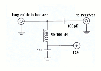
The circuit use only one transistor, but it gives you 10 to 15 dB amplification, enough for many situation. The most important part is that the transistor circuitry should be shielded from the input circuitry, as shown in the schematic diagram by the dashed line. This ircuit is powered via the signal cable, since the antenna booster circuit must be wired as close as possible to the antenna. This is very important since the amplifier should amplify the signal acquired by the antenna, not the noise picked by the cable from the antenna to the circuit. The antenna and the booster circuit can be installed above your house’s roof. Long 75 ohm coaxial cable can be drawn from the this booster circuit output to the power supply unit close to TV set.


Just insert a 50-10o uH inductor or RF choke between the output cable and the power supply. Tap the output signal from the output cable using a small 100pF ceramic capacitor to block the DC voltage from the power supply. Adjust P1 to get the best reception, and this should set the working current consumption to around 5-15 mA.

source :http://freecircuitdiagram.com/2009/05/30/uhf-antenna-booster/

READ MORE...

10 Watt Car Audio Amplifier

10 Watt Car Audio Amplifier

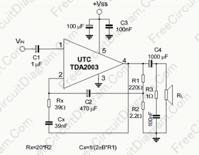
TDA2003 is audio amplifier integrated circuit chip in 10 Watt class. All you need is just adding few passive components and your amplifier will be ready. You can even amplify ultrasonic range if you wish to abuse its usage, just to convince you that this chip is more than enough to handle any range of audio signal. Although many manufacturer produce this TDA2003 chip, in general, this various chip from various manufacturer normally comply with these following features: Short circuit protection between all pins, High current output ( up to 3 A), Built-in Over temperature protection, and Low harmonic and crossover distortion.


source :http://freecircuitdiagram.com/2008/08/04/10-watt-car-audio-amplifier/
READ MORE...

Car Stereo Booster with LM2896

Car Stereo Booster with LM2896

This car stereo booster uses an LM2896 IC which has two integrated amplifiers. It can be powered with voltages up to 15 volts. The power output is 2.5 watts per channel with an 8 Ω load and supply voltage of 12 volts. Using the bridge tehnique in the circuit gives a power output of 9 watts. The car audio booster can be powered up from 3 up to 15 volts.

Car stereo booster circuit diagram

The load impedance that can be connected at its output can be either 4 Ω or 8 Ω. The supply voltage and the load impedance influence the output power level. This amplifier circuit is designed as a booster for auto radio/cassette players. The current consumption by maximum power output and a 4 Ω load is 1 ampere.


more info and source : http://mycaramplifiers.com/car-stereo-booster-with-lm2896-395.html READ MORE...

Car Stereo Booster with LM2896

Car Stereo Booster with LM2896

This car stereo booster uses an LM2896 IC which has two integrated amplifiers. It can be powered with voltages up to 15 volts. The power output is 2.5 watts per channel with an 8 Ω load and supply voltage of 12 volts. Using the bridge tehnique in the circuit gives a power output of 9 watts. The car audio booster can be powered up from 3 up to 15 volts.

Car stereo booster circuit diagram

The load impedance that can be connected at its output can be either 4 Ω or 8 Ω. The supply voltage and the load impedance influence the output power level. This amplifier circuit is designed as a booster for auto radio/cassette players. The current consumption by maximum power output and a 4 Ω load is 1 ampere.


more info and source : http://mycaramplifiers.com/car-stereo-booster-with-lm2896-395.html READ MORE...

200 watts amplifier TDA2030


TDA 2030 is produced by SGS Ates and is a complete audio amplifier. AB class of the final amplifier cand deliver up to 14W on 4 ohm at a +-14V power supply.


Connecting two TDA2030 thru cheap power transistors we can create a amplifier wich can deliver a higher power. With the components value from the schematic the total amplifier gain is 32 dB. The speaker can be 2 ohm instead of 4 ohm if we use the TIP transistors. With a proper designed power supply this audio amplifier can output 200W.
 
Active components:


IC1, Ic2 TDA 2030

T1, T3 = BD 250, TIP 36

T2,T4 = BD 249, TIP 35

D1 … D4 = 1N4001
source:http://mycaramplifiers.com/200-watts-amplifier-tda2030-8.html READ MORE...

amplificador operacional

LM 741 .- Amplificador Operacional


National


Semiconductor


LM741/LM741A/LM741C/LM741E Operational Ampiifier


General Description


The LM741 series are general purpose operational amplifi-


ers which feature improved performance over industry stan-


dards like the LM709. They are direct, plug-in replacements


for the 709C, LM201, MC1439 and 748 in most applications.


The amplifiers offer many features which make their appli-


cation nearly foolproof: overload protection on the input and
 
output, no latch-up when the common mode range is ex-


ceeded, as well as freedom from oscillations.


The LM741C/LM741E are identical to the LM741/LM741A


except that the LM741C/LM741E have their performance


guaranteed over a 0°C to f 70°C temperature range, in-


stead of - 55°C to ! 125°C
 
download  datasheet LM 741 .- Amplificador Operacional National Semiconductor READ MORE...

Two Transistors Wireless Microphone FM Transmitter Circuit Schematic Diagram

Two Transistors Wireless Microphone FM Transmitter Circuit Schematic Diagram

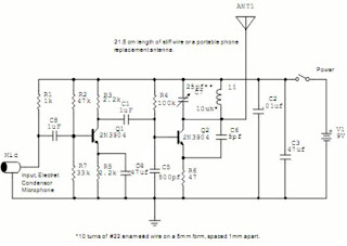
Please be warned if operating this circuit might violate the regulation of your country, because this FM transmitter circuit radiate strong radio frequency to the environment. This wireless microphone is very sensitive, pick up every sound in the 20m radius, and transmit the radio signal up to 2 kilometers in open air. Here is the schematic diagram of the circuit:


The first transistor (Q1) is the pre-amplifier for the microphone, and you can ommit this circuit if you don’t want to transmit the sound picked up by the mic, for example you can can connect your mp3 player directly to C1. The core of this FM transmitter circuit is Q2, a modified Collpits oscillator that the frequency is determined by L1, C4, C6, and the transistor’s internal base-emitter capacitance. The antenna use 1/16 wave length to compromize between the efficiency and the size. If you want the microphone to be less sensitive, you can replace the R1 by a higher resistor, try 10k or 22k, and this might overcome the feedback problem if you use this wireless microphone FM transmitter for a public address system. READ MORE...

Two Transistors Wireless Microphone FM Transmitter Circuit Schematic Diagram

Two Transistors Wireless Microphone FM Transmitter Circuit Schematic Diagram

Please be warned if operating this circuit might violate the regulation of your country, because this FM transmitter circuit radiate strong radio frequency to the environment. This wireless microphone is very sensitive, pick up every sound in the 20m radius, and transmit the radio signal up to 2 kilometers in open air. Here is the schematic diagram of the circuit:


The first transistor (Q1) is the pre-amplifier for the microphone, and you can ommit this circuit if you don’t want to transmit the sound picked up by the mic, for example you can can connect your mp3 player directly to C1. The core of this FM transmitter circuit is Q2, a modified Collpits oscillator that the frequency is determined by L1, C4, C6, and the transistor’s internal base-emitter capacitance. The antenna use 1/16 wave length to compromize between the efficiency and the size. If you want the microphone to be less sensitive, you can replace the R1 by a higher resistor, try 10k or 22k, and this might overcome the feedback problem if you use this wireless microphone FM transmitter for a public address system. READ MORE...

Metal Detector Circuit Schematic using Beat Frequency Oscillator (BFO)

Metal Detector Circuit Schematic using Beat Frequency Oscillator (BFO)

The simplest method of detecting metal is by beat frequency oscillator. The circuit basically consists of two balanced oscillator. One acts as the detector element, the other provides the reference signal. This oscillator frequency reference is set to fix value, whilst the detector oscillator varies depending on the metal presence. The reference oscillator can be constructed using various circuit topology: inductor-capacitor (LC), resistor-capacitor (RC), or even a crystal (quartz) oscillator. While the reference oscillator can be implemented using various circuit topology, the detector oscillator always use inductor-capacitor topology, because the mechanism will be using the magnetic induction property of the detected object, and the inductor component of the detector oscillator will be the detecting probe.


With the absence of a metal near the detector probe (the inductor component of the detector oscillator), the detector oscillator is tuned to have same frequency as the reference oscillator. The output of the detector oscillator and the reference oscillator output is mixed using hetero-dyne mixer circuit, producing a beat frequency output of zero Hz, or a very low frequency if both oscillator is slightly unbalanced. In the presence of a metal near the detector probe, the detector oscillator will shift it’s frequency, and the mixer output will produce a tone with frequency equal to the difference of the reference and the detector frequency.


The figure below shows one of the simple metal detector circuit.You can see the reference circuit is a simple RC circuit, and its frequency is determined by R1-P2-C1. The detector oscillator is an LC oscillator with the frequency is determined by the L1-C2-C3 values.


The NAND gates use CMOS 4011 chip, a low power component that is suitable for this battery-operated circuit. You can see that this chip is supplied by a 5V voltage coming from an LM7805L regulator. You might wonder what the purpose of this regulation is, since the power supply come from a 9V battery and the CMOS gates can handle the voltage of 3-15 Volt. The main purpose of the regulator is to keep a constant voltage source for the reference oscillator frequency stability, since the frequency is affected by the power supply voltage variation as the battery voltage drops in the long time of usage.


Here the complete parts list:


Parts list:

U1: CD4011

U2: LM389

U3: 78L05

R1: 2.2k 5%

P2: 4.7k lin.

R3: 330k 5%

R4: 270k 5%

R5: 1k 5%

C1: 390pF (NPO)

C2,C3,C4: 10nF

C5: 10uF 16v electrolytic

C6,C8: 220 uF 16v electrolytic

C7: 100uf 16v electrolytic

C9: 100nF ceramic

P1: 4.7k log

L1: 22cm in diameter with 14 turns AWG 26

K1: SPDT toggle switch

J1= Headphone jack 1/4 or 1/8 inch

Other parts: 9v battery connector, speaker or headphones


To tune the circuit, plug a headphone at the output, and remove any metal around the inductor L1. Set the volume control P1 around at center. Set the reference oscillator tuner P2 at the maximum or minimum position, you should hear no sound since the frequency should be in ultrasonic range. Turn slowly P2 until you hear a very high audio frequency, continue turning the pot until the frequency is decreasing and stop turning when the note is just disappeared (the frequency is decreased down below 20 Hz). After this, you can test the circuit by placing a metal near the inductor L1 and now the output will give an audible frequency as the detection alert. [Circuit schematic diagram source: hobby-hour.com] READ MORE...