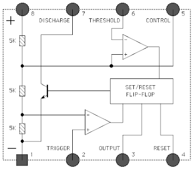
This folio presents accepted advice and tips for application the LM555 timer and its cousins with added letter prefixes. There can be accessory differences amid 555 timer IC's from altered manufacturers but they all should be adapted for any ambit on this page.

If you would like to use any of these ideas, amuse booty time to do some testing afore application the LM555 timer in an absolute circuit. All of the solutions on this folio can additionally be activated to the LM556 - Dual timer.

Some of the circuits on this folio were developed aloof to see if they would assignment and accept no advised use.
The card beneath links to assorted sections of this folio that chronicle to the items in the index. New additions arise at the basal of the list.This page does not apply the LM558 - Quad Timer IC which is significantly different when compared to the 555 and 556 timers.
The differences include: (1) The output of each 558 timer is an open collector transistor with a 100 milliamp current capacity while the 555 and 556 timers have bipolar outputs with a 200 milliamp capacity. (2) The TRIGGER input of the 558 is EDGE Triggered while the TRIGGER input of the 555 and 556 timers are LEVEL Triggered.
Individual LM558 timers are not designed to operate in an astable mode. Two 558 timers must be connected in a loop to make an astable oscillator.
EDGE Triggered - means that the change in the output state of the timer is caused by a quickly falling or rising voltage at the input terminal. If the input voltage changes too slowly the output will not switch states.
LEVEL Triggered - means that the change in the output state of the timer is caused when the voltage at an input terminal falls bellow or rises above a preset level. The rate at which the voltage changes is not a factor.
The THRESHOLD input terminals for the 555, 556 and 558 timers are all LEVEL triggered.
